Sunday, 24 June 2012

12V Speed Controller/Dimmer

This handy circuit can be used as a speed controller for a 12V motor rated up to 5A (continuous) or as a dimmer for a 12V halogen or standard incandescent lamp rated up to 50W. It varies the power to the load (motor or lamp) using pulse width modulation (PWM) at a pulse frequency of around 220Hz.


SILICON CHIP has produced a number of DC speed controllers over the years, the most recent being our high-power 24V 40A design featured in the March & April 2008 issues. Another very popular design is our 12V/24V 20A design featured in the June 1997 issue and we have also featured a number of reversible 12V designs.

Circuit looks like:
12V motor speed controller or lamp dimmer schematic circuit


For many applications though, most of these designs are over-kill and a much simpler circuit will suffice. Which is why we are presenting this basic design which uses a 7555 timer IC, a Mosfet and not much else. Being a simple design, it does not monitor motor back-EMF to provide improved speed regulation and nor does it have any fancy overload protection apart from a fuse. However, it is a very efficient circuit and the kit cost is quite low.

Parts layout:

Parts layout of 12 volt speed controller or lamp dimmer
Connection diagram:
Layout while connecting motor to the circuit

There are many applications for this circuit which will all be based on 12V motors, fans or lamps. You can use it in cars, boats, and recreational vehicles, in model boats and model railways and so on. Want to control a 12V fan in a car, caravan or computer? This circuit will do it for you.

Circuit diagram:
12V speed controller or lamp dimmer circuit diagram

The circuit uses a 7555 timer (IC1) to generate variable width pulses at about 210Hz. This drives Mosfet Q3 (via transistors Q1 & Q2) to control the speed of a motor or to dim an incandescent lamp.

Halogen lamps:

While the circuit can dim 12V halogen lamps, we should point out that dimming halogen lamps is very wasteful. In situations where you need dimmable 12V lamps, you will be much better off substituting 12V LED lamps which are now readily available in standard bayonet, miniature Edison screw (MES) and MR16 halogen bases. Not only are these LED replacement lamps much more efficient than halogen lamps, they do not get anywhere near as hot and will also last a great deal longer.


Transformerless Power Supply

This circuit will supply up to about 20ma at 12 volts. It uses capacitive reactance instead of resistance; and it doesn't generate very much heat.The circuit draws about 30ma AC. Always use a fuse and/or a fusible resistor to be on the safe side. The values given are only a guide. There should be more than enough power available for timers, light operated switches, temperature controllers etc, provided that you use an optical isolator as your circuit's output device. (E.g. MOC 3010/3020) If a relay is unavoidable, use one with a mains voltage coil and switch the coil using the optical isolator.C1 should be of the 'suppressor type'; made to be connected directly across the incoming Mains Supply.


They are generally covered with the logos of several different Safety Standards Authorities. If you need more current, use a larger value capacitor; or put two in parallel; but be careful of what you are doing to the Watts. The low voltage 'AC' is supplied by ZD1 and ZD2. The bridge rectifier can be any of the small 'Round', 'In-line', or 'DIL' types; or you could use four separate diodes. If you want to, you can replace R2 and ZD3 with a 78 Series regulator. The full sized ones will work; but if space is tight, there are some small 100ma versions available in TO 92 type cases. They look like a BC 547. It is also worth noting that many small circuits will work with an unregulated supply.


Circuit diagram:
Transformerless Power Supply Circuit Diagram


You can, of course, alter any or all of the Zenner diodes in order to produce a different output voltage. As for the mains voltage, the suggestion regarding the 110v version is just that, a suggestion. I haven't built it, so be prepared to experiment a little. I get a lot of emails asking if this power supply can be modified to provide currents of anything up to 50 amps. It cannot. The circuit was designed to provide a cheap compact power supply for Cmos logic circuits that require only a few milliamps. The logic circuits were then used to control mains equipment (fans, lights, heaters etc.) through an optically isolated triac.


If more than 20mA is required it is possible to increase C1 to 0.68uF or 1uF and thus obtain a current of up to about 40mA. But 'suppressor type' capacitors are relatively big and more expensive than regular capacitors; and increasing the current means that higher wattage resistors and zener diodes are required. If you try to produce more than about 40mA the circuit will no longer be cheap and compact, and it simply makes more sense to use a transformer. The Transformer less Power Supply Support Material provides a complete circuit description including all the calculations.


Web-masters Note:
I have had several requests for a power supply project without using a power supply. This can save the expense of buying a transformer, but presents potentially lethal voltages at the output terminals. Under no circumstances should a beginner attempt to build such a project.


Important Notice:
Electric Shock Hazard. In the UK,the neutral wire is connected to earth at the power station. If you touch the "Live" wire, then depending on how well earthed you are, you form a conductive path between Live and Neutral. DO NOT TOUCH the output of this power supply. Whilst the output of this circuit sits innocently at 12V with respect to (wrt) the other terminal, it is also 12V above earth potential. Should a component fail then either terminal will become a potential shock hazard.


MAINS ELECTRICITY IS VERY DANGEROUS.


If you are not experienced in dealing with it, then leave this project alone. Although Mains equipment can itself consume a lot of current, the circuits we build to control it, usually only require a few milliamps. Yet the low voltage power supply is frequently the largest part of the construction and a sizeable portion of the cost.


Author: Ron J - Copyright: Zen

3V Supply Splitter


Many modern circuits tend to work from a single supply voltage of 3V. But often they need a virtual earth at half the supply voltage for efficient operation. The splitter shown in the diagram bisects the supply voltage with a high-resistance potential divider, R1-R2, and buffers the resulting 1.5 V line with an op amp. Since the op amp used is not a fast type, the output is decoupled by capacitive divider C2-C3. This ensures that the impedance of the virtual earth point remains low over a wide frequency band. Because the potential at the junction C2-C3-R3 is fed back to the inverting input of IC1, the circuit becomes a standard voltage follower.

Resistor R3 ensures that the regulation remains stable. The circuit can regulate ±2mA without any difficulties. Because of the low current drawn by IC1, and the high resistance of R1 and R2, the overall current drain is low. In the absence of a load, it was 13µA in the prototype, of which 1.5µA flows through R1-R2. Finally, since IC1 can operate from a voltage as low as 1.6V, the splitter will remain fully operational when the battery nears the end of its charge or life.

Mains Frequency Monitor

Here is a simple frequency counter designed to monitor the 240VAC mains supply. It as a frequency range of 0-999Hz, so it could also be used with 400Hz equipment. Standard TTL/CMOS logic is employed for the counters and display drivers, while an ELM446 (IC1) generates accurate 1Hz pulses for gating. This device utilizes a 3.579545MHz crystal for its timebase, as commonly found in TV and video circuits and even on old PC motherboards.


Circuit diagram:
Mains frequency monitor circuit schematic
Copyright: Silicon Chip Electronics Magazine

Non-Contact Power Monitor

Here is a simple non-contact AC power monitor for home appliances and laboratory equipment that should remain continuously switched-on. A fuse failure or power breakdown in the equipment going unnoticed may cause irreparable loss. The monitor sounds an alarm on detecting power failure to the equipment. The circuit is built around CMOS IC CD4011 utilising only a few components. NAND gates N1 and N2 of the IC are wired as an oscillator that drives a piezobuzzer directly. Resistors R2 and R3 and capacitor C2 are the oscillator components. The amplifier comprising transistors T1 and T2 disables the oscillator when mains power is available. In the standby mode, the base of T1 picks up 50Hz mains hum during the positive half cycles of AC and T1 conducts.

Contactless Power Monitor Circuit Diagram
This provides base current to T2 and it also conducts, pulling the collector to ground potential. As the collectors of T1 and T2 are connected to pin 2 of NAND gate N1 of the oscillator, the oscillator gets disabled when the transistors conduct. Capacitor C1 prevents rise of the collector voltage of T2 again during the negative half cycles. When the power fails, the electrical field around the equipment’s wiring ceases and T1 and T2 turn off. Capacitor C1 starts charging via R1 and preset VR and when it gets sufficiently charged, the oscillator is enabled and the piezobuzzer produces a shrill tone. Resistor R1 protects T2 from short circuit if VR is adjusted to zero resistance.


The circuit can be easily assembled on a perforated/breadboard. Use a small plastic case to enclose the circuit and a telescopic antenna as aerial. A 9V battery can be used to power the circuit. Since the circuit draws only a few microamperes current in the standby mode, the battery will last several months. After assembling the circuit, take the aerial near the mains cable and adjust VR until the alarm stops to indicate the standby mode. The circuit can be placed on the equipment to be monitored close to the mains cable.


12 Volt DC Fluorescent Lamp Driver

A number of people have been unable to find the transformer needed for the Black Light project, so I looked around to see if I could find a fluorescent lamp driver that does not require any special components. I finally found one in Electronics Now. Here it is. It uses a normal 120 to 6V stepdown transformer in reverse to step 12V to about 350V to drive a lamp without the need to warm the filaments.

12 Volt DC Fluorescent Lamp Driver circuit diagram

Components List

C1 100uf 25V Electrolytic Capacitor
C2,C3 0.01uf 25V Ceramic Disc Capacitor
C4 0.01uf 1KV Ceramic Disc Capacitor
R1 1K 1/4W Resistor
R2 2.7K 1/4W Resistor
Q1 IRF510 MOSFET
U1 TLC555 Timer IC
T1 6V 300mA Transformer
LAMP 4W Fluorescent Lamp
MISC Board, Wire, Heatsink For Q1

Notes:
  1. Q1 must be installed on a heat sink.
  2. A 240V to 10V transformer will work better then the one in the parts list. The problem is that they are hard to find.
  3. This circuit can give a nasty (but not too dangerous) shock. Be careful around the output leads.

Copyright: http://www.extremecircuits.net

Efficient Fan Speed Controller

A partial solution to quietening noisy PCs can be to reduce the speed of internal cooling fans. Low-cost fan speed controllers are available, but they often employ inefficient, heat-generating linear regulators and contain no temperature feedback mechanism. This idea makes use of a readily available, cheap in-car mobile phone charger. The majority of these use common circuitry and require only minor modifications to operate as efficient fan speed controllers complete with temperature feedback. Most in-car chargers are based on the well-known MC34063 DC-DC switchmode IC.


When used for charging mobile phones, the open-circuit output voltage is typically set to between 7V and 9V. This is achieved with a simple voltage divider across the output, the centre point of which connects to the feedback input (pin 5) of the MC34063. To make the output voltage var-iable with air temperature, first replace the upper resistor of the divider with a 4.7kΩ resistor in series with a 4.7kΩ trimpot. The lower half of the divider is then replaced with a 470Ω resistor in series with a 500Ω NTC thermistor. These values are only a guide and can be varied to suit different thermistor and fan types.

Circuit diagram:
Efficient fan speed controller circuit schematic

Note that component lead length should be minimised to avoid introducing noise into the feedback circuitry. Getting the correct fan starting voltage is a matter of trial and error. The values shown on the circuit give a starting voltage of about 6.8V at room temperature but trimpot VR1 can be used to raise this voltage as necessary. The output can then rise to about 10V if the interior temperature rises sufficiently. The 4.7kΩ resistor could be reduced to 3.9kΩ and VR1 adjusted to give a lower starting voltage if the fan speed is still too high at 7V. After running for one hour or so, the fan voltage as set by the interior case temperature thermistor on my PC settled at 7.4V.

Suitable chargers are available from Oatley Electronics, Cat. No. 2D0074. They’re currently listed at $5 for two, which is less than the price of the MC34063 ICs alone! Data on the MC34063 can be downloaded from www.onsemi.com and a useful development aid is to be found at www.nomad.ee/micros/mc34063. Finally, note that not all chargers have an output filter capacitor installed. Typically, this is a 220µF 10V or 16V electrolytic type. To save a few cents, the manufacturers sometimes leave this component out, relying on the mobile’s battery to perform the filtering task. If this component is missing from your charger’s PC board, it should be installed before the supply is used.

Author: Brad Sheargold

Copyright: Silicon Chip Electronics

Fan Controller Using Just Two Components

The Maxim MAX 6665 (www.maxim-ic.com) provides a complete temperature-dependent fan controller. It can switch fans operating at voltages of up to 24 V and currents of up to 250 mA. The IC is available from the manufacturer in versions with preset threshold temperatures between +40 °C (MAX6665 ASA40) and +70 °C (MAX6665 ASA 70). The device’s hysteresis can be set by the user via the HYST input, which can be connected to +3.3 V, connected to ground, or left open. The following table shows the hysteresis values available:


HYST = Hysteresis
open = 1 °C
ground = 4 °C
+3.3V = 8 °C
Fan Controller Circuit Diagram

The other pins of the SO8 package are the FORCEON input and the status outputs WARN, OT and FANON. The test input FORCEON allows the fan to be run even below the threshold temperature. The open-drain output WARN goes low when the temperature rises more than 15 °C above the threshold temperature, while the open-drain output OT indicates when the temperature is more than 30 °C above the threshold. The push-pull output FANON can be used to indicate to a connected microcontroller that the fan is turned on.

Author: G. Kleine

Copyright: Elektor Electronics

Ultra Bright LED Lamp

This ultra-bright white LED lamp works on 230V AC with minimal power consumption. It can be used to illuminate VU meters, SWR meters, etc. Ultra-bright LEDs available in the market cost Rs 8 to 15. These LEDs emit a 1000-6000mCd bright white light like welding arc and work on 3 volts, 10 mA. Their maximum voltage is 3.6 volts and the current is 25 mA. Anti-static precautions should be taken when handling the LEDs.

The LEDs in water-clear plastic package emit spotlight, while diffused type LEDs have a wide-angle radiation pattern. This circuit (Fig. 1) employs capacitive reactance for limiting the current flow through the LEDs on application of mains voltage to the circuit. If we use only a series resistor for limiting the current with mains operation, the limiting resistor itself will dissipate around 2 to 3 watts of power, whereas no power is dissipated in a capacitor. The value of capacitor is calculated by using the following relationships:

  • XC = 1/(2pfC) ohms —————(a)
  • XC = VRMS /I ohms ———— (b)
where XC is capacitive reactance in ohms, C is capacitance in farads, I is the current through the LED in amperes, f is the mains frequency in Hz, and Vrms is the input mains voltage. The 100-ohm, 2W series resistor avoids heavy ‘inrush’ current during transients. MOV at the input prevents surges or spikes, protecting the circuit. The 390-kilo-ohm, ½-watt resistor acts as a bleeder to provide discharge path for capacitor Cx when mains supply is disconnected.

Circuit diagram:
ultra bright LED lamp circuit schematic

The zener diode at the output section prevents excess reverse voltage levels appearing across the LEDs during negative half cycles. During positive half cycle, the voltage across LEDs is limited to zener voltage. Use AC capacitors for Cx. Filter capacitor C1 across the output provides flicker-free light. The circuit can be enclosed in a CFL round case, and thus it can be connected directly to AC bulb holder socket.

A series combination of 16 LEDs (Fig. 2) gives a luminance (lux) equivalent of a 12W bulb. But if you have two series combinations of 23 LEDs in parallel (total 46 LEDs as shown in Fig. 3), it gives light equal to a 35W bulb. 15 LEDs are suitable for a table-lamp light. Diode D1 (1N4007) and capacitor C1 act as rectifying and smoothing elements to provide DC voltage to the row of LEDs. For a 16-LED row, use Cx of 0.22 µF, 630V; C1 of 22 µF, 100V; and zener of 48V, 1W. Similarly, for 23+23 LED combination use Cx of 0.47 mF, 630V; C1 of 33 µF, 150V; and zener of 69V, 1W. This circuit (inclusive 


of LEDs) costs Rs 200 to Rs 400.
Source: EFY Mag

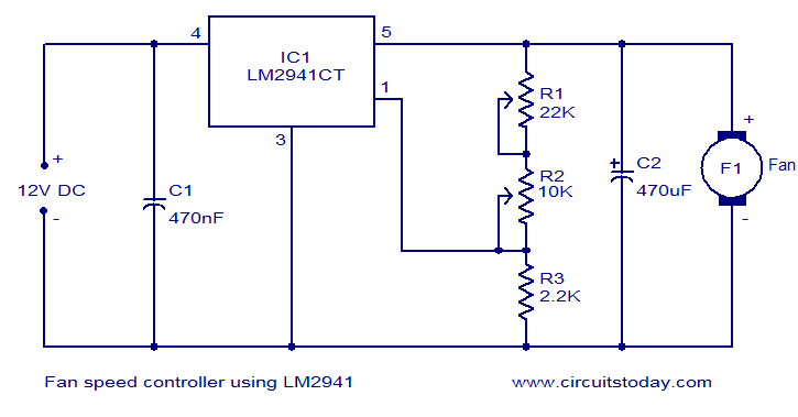
Fan speed controller using LM2941


Description.
Many electronic circuits related to fan speed controlling have been published here and this one is just another approach. The circuit diagram shown here is of 12V DC fan speed controller using the IC LM2941CT which is a low drop out 1A voltage regulator. The IC has a dropout voltage as low as 0.5 and has also many useful features like power supply reverse protection, thermal protection, short circuit protection etc. The maximum output current the IC can source is 1A.
The 12V DC supply is connected between the Vin (pin4) and ground (pin3) of the IC. The load, which is the fan, is connected across the Vout (pin5) and ground (pin3) of the IC. The network comprising of potentiometers R1, R2 and resistor determines adjust current (Iadj) of the IC. By varying the Iadj using the POT R2 we can adjust the output voltage of the IC and hence the fan speed.
Circuit diagram.
fan speed controller using LM2941
Notes.
  • The circuit can be powered from 12V DC.
  • The maximum possible load current is 1A.
  • A heat sink is recommended for the IC.


  • POT R1 can be used to adjust the minimum fan sp
  • POT R2 can be used to adjust the fan speed.

Saturday, 23 June 2012

12V Flourescent Lamp Inverter


Fluorescent tubes use far less energy than incandescent lamps and fluorescent tubes last a great deal longer as well. Other advantages are diffuse, glare-free lighting and low heat output. For these reasons, fluorescent lighting is the natural choice in commercial and retail buildings, workshops and factories. For battery-powered lighting, fluorescent lights are also the first choice because of their high efficiency. The main drawback with running fluorescent lights from battery power is that an inverter is required to drive the tubes.


Circuit diagram:

12V Flourescent Lamp Inverter circuit schematic


Fig.1: two switch-mode circuits are involved here: the DC-DC inverter involving IC1, Q1 & Q2 and the fluoro tube driver which converts high voltage DC to AC via IC3 and Q3 & Q4 in a totem-pole circuit.

Inverter efficiency then becomes the major issue. There are many commercial 12V-operated fluorescent lamps available which use 15W and 20W tubes. However, it is rare to see one which drives them to full brilliance. For example, a typical commercial dual 20W fluorescent lamp operating from 12V draws 980mA or 11.8W. Ignoring losses in the fluorescent tube driver itself, it means that each tube is only supplied with 5.9W of power which is considerably less than their 20W rating. So while the lamps do use 20W tubes, the light output is well below par.

Warning:
This circuit generates in excess of 300V DC which could be lethal. Construction should only be attempted by those experimenced with mains-level voltages and safety procedures.

Supply Voltage Indicator


This simple and slightly odd circuit can clearly show the level of the supply voltage (in a larger device): as long as the indicator has good 12 volts at its input, LED1 gives steady, uninterrupted (for the naked eye) yellow light. If the input voltage falls below 11 V, LED1 will start to blink and the blinking will just get slower and slower if the voltage drops further - giving very clear and intuitive representation of the supply's status. The blinking will stop and LED1 will finally go out at a little below 9 volts. On the other hand, if the input voltage rises to 13 V, LED2 will start to glow, getting at almost full power at 14 V. The characteristic voltages can be adjusted primarily by adjusting the values of R1 and R4. The base-emitter diode of T2 basically just stands in for a zener diode.


Circuit diagram:


The emitter-collector path of T1 is inversely polarized and if the input voltage is high enough - T1 will cause oscillations and the frequency will be proportional to the input voltage. The relaxation oscillator ceases cycling when the input voltage gets so low that it no longer can cause breakdown along the emitter-collector path. Not all small NPN transistors show this kind of behavior when inversely polarized in a similar manner, but many do. BC337-40 can start oscillations at a relatively low voltage, other types generally require a volt or two more. If experimenting, be careful not to punch a hole through the device under test: they oscillate at 9-12 V or not at all.

Compact High-Performance 12V 20W Stereo Amplifier

Amplifiers which run from 12V DC generally don’t put out much power and they are usually not hifi as well. But this little stereo amplifier ticks the power and low distortion boxes. With a 14.4V supply, it will deliver 20 watts per channel into 4-ohm loads at clipping while harmonic distortion at lower power levels is typically less than 0.03%.

This is an ideal project for anyone wanting a compact stereo amplifier that can run from a 12V battery. It could be just the ticket for buskers who want a small but gutsy amplifier which will run from an SLA battery or it could used anywhere that 12V DC is available – in cars, recreational vehicles, remote houses with 12V DC power or where ever.

12 Volt 20W Stereo Amplifier circuit schematic

Because it runs from DC, it will be an ideal beginner’s or schoolie’s project, with no 240VAC power supply to worry about. You can run it from a 12V battery or a DC plugpack. But while it may be compact and simple to build, there is no need to apologise for “just average” performance. In listening tests from a range of compact discs, we were very impressed with the sound quality.

Long-time readers might recall that we presented a similar 12V power amplifier design back in May 2001. It was a similar configuration to this one but it is now completely over-shadowed by the much lower distortion and greatly improved signal-to-noise ratio of this new design. In fact, let’s be honest: the previous unit is not a patch on this new design. It used two TDA1519A ICs which resulted in distortion figures above 1% virtually across the board and a signal-to-noise ratio of only -69dB unweighted.

However, by using the TDA­7377 power amplifier IC and making some other improvements, the THD (total harmonic distortion) of the new design is about 50 times better than the older unit (see performance graphs for details). The bottom line is that the THD under typical conditions is around just 0.03% or less. It is also able to deliver more output power due to the improved output transistors in the new power amplifier IC.

In addition, its idle power consumption is low – not much more than 1W. As a result, if you don’t push it too hard it will run cool and won’t drain the battery too quickly. And because the IC has self-protection circuitry, it’s just about indestructible. It will self-limit or shut down if it overheats and the outputs are deactivated if they are shorted.

Circuit diagram:
12V 20W Stereo Amplifier circuit schematic

With a 12V supply, the largest voltage swing a conventional solid-state power amplifier can generate is ±6V. This results in a meagre 4.5W RMS into 4O and 2.25W RMS into 8O, without considering losses in the output transistors. Even if the DC supply is around 14.4V (the maximum that can normally be expected from a 12V car battery), that only brings the power figures up to 6.48W and 3.24W for 4O and 8O loads respectively – still not really enough.

There are three common solutions to this problem. The first is to boost the supply voltage using a switchmode DC converter. This greatly increases the cost and complexity of the amplifier but it is one way of getting a lot of power from a 12V supply. However, we wanted to keep this project simple and that rules out this technique.

There are variations on the boosting method, such as the class H architecture used in the TDA1562Q IC featured in the Portapal PA Amplifier (SILICON CHIP, February 2003). It is able to achieve 40W/channel but with >0.1% THD. In that case, the amplifier output itself provides the switching for a charge pump. The second method is to lower the speaker impedance. Some car speakers have an impedance as low as 2O, which allows twice as much power to be delivered at the same supply voltage. However, we don’t want to restrict this amplifier to 2O loudspeakers.

Author: Nicholas Vinen - Copyright: Silicon Chip